Cash Drawer
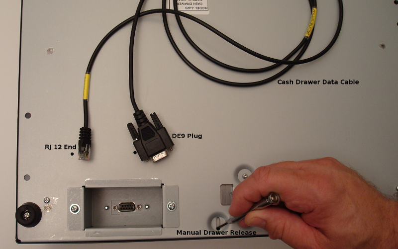
Shown here is an MS cash drawer (model J-423) with the Epson data cable (CD9-Epson-NCMS). This cable is used with an Epson receipt printer to "kick out" the cash drawer. The cable has an RJ12 connection at one end, which resembles a phone jack, and a DE9 plug at the other. The DE9 fits directly into the cash drawer, and the RJ12 will connect to the back of the Epson printer. There is also a manual drawer release lever on the bottom of the drawer which can be triggered using a small screwdriver, toothpick, paperclip, etc.
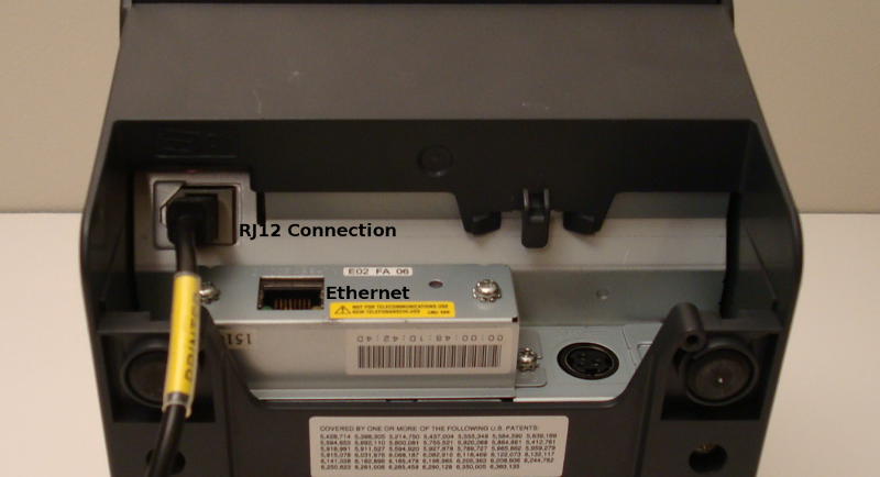
RJ12
This photo illustrates the correct installation of the RJ12 cable on an Epson TM-T88V. Be sure not to confuse the RJ12 connection with the ethernet connection on the printer as both connectors will physically fit in either position. The location of the RJ12 connection will vary depending on which model of Epson printer you are using.t
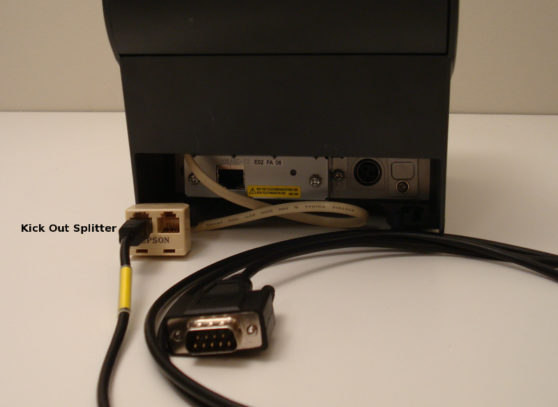
Kick Out Splitter
MS manufactures a kick out splitter (Epson-RJ-Y-CABL) that allows you to open two separate drawers using the same printer. It is a RJ12 to RJ12 connector and will plug into the same place on the back of the printer as described above.
Keys
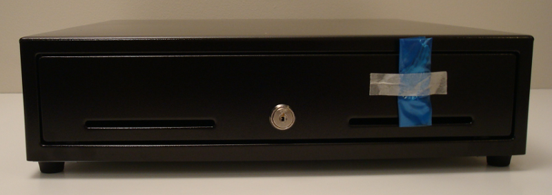
MS ships their cash drawers with the keys taped securely to the drawer housing. There is no need to keep track of multiple keys for multiple drawers, as they are all keyed alike. As long as you continue to use the MS brand and J-423 model, your key will always work. Should you need replacement keys for your cash drawer, please contact your hardware vendor or MS directly at www.mscashdrawer.com. To open the drawer, insert the key flat side down and rotate it clockwise (right).
Parallel Cash Drawers
Parallel cash drawers have slightly different components than the Epson compatible drawers shown above. A parallel drawer requires an external power supply to kick out the drawer, specific dip switch settings, and a terminator fitted to the parallel cable. Using parallel to open drawers will allow multiple drawers to be chained together at the same terminal.
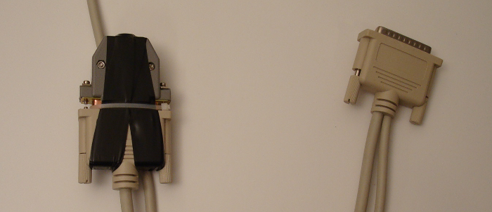
A parallel cable is shown in the image above. Notice the plug on the right side has two cables running out of it. This is the cable that will plug into the computer. The left plug will be connected to a terminator as shown here, or if chaining multiple drawers together, another parallel cable would be used with a terminator installed on the last drawer in that chain. A terminator is required regardless of whether you are using a single drawer or multiple drawers. The drawer will not kick out without a terminator in place.
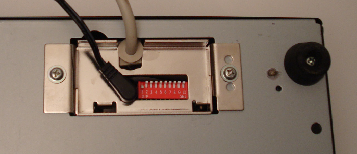
Shown here is the bottom of a parallel cash drawer. This end of the parallel cable is fixed to the drawer. There is a 24v power connection as well as a dip switch. See the chart below for the proper dip switch settings.
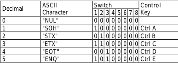
Dip Switch Settings For Parallel Cash Drawers
This chart represents the dip switch settings needed to make use of parallel drawer opening. Set your drawer's dip switch to the matching setting under the Device column in Add/Edit Cash Drawers. For example, if parallel -1 is selected under Device, your dip switch setting would need to be: switch 1 "on" and switch 2-8 "off" as shown in the picture above.